|
§ 194.44 Engineered Barriers
(a) Disposal systems shall incorporate engineered barrier(s) designed to prevent or substantially delay the movement of water or radionuclides toward the accessible environment.
(b) In selecting any engineered barrier(s) for the disposal system, DOE shall evaluate the benefit and detriment of engineered barrier alternatives, including but not limited to: cementation, shredding, supercompaction, incineration, vitrification, improved waste canisters, grout and bentonite backfill, melting of metals, alternative configurations of waste placements in the disposal system, and alternative disposal system dimensions. The results of this evaluation shall be included in any compliance application and shall be used to justify the selection and rejection of each engineered barrier evaluated.
(c)(1) In conducting the evaluation of engineered barrier alternatives, the following shall be considered, to the extent practicable:
(i) The ability of the engineered barrier to prevent or substantially delay the movement of water or waste toward the accessible environment;
(ii) The impact on worker exposure to radiation both during and after incorporation of engineered barriers;
(iii) The increased ease or difficulty of removing the waste from the disposal system;
(iv) The increased or reduced risk of transporting the waste to the disposal system;
(v) The increased or reduced uncertainty in compliance assessment;
(vi) Public comments requesting specific engineered barriers;
(vii) The increased or reduced total system costs;
(viii) The impact, if any, on other waste disposal programs from the incorporation of engineered barriers (e.g., the extent to which the incorporation of engineered barriers affects the volume of waste);
(ix) The effects on mitigating the consequences of human intrusion.
(2) If, after consideration of one or more of the factors in paragraph (c)(1) of this section, DOE concludes that an engineered barrier considered within the scope of the evaluation should be rejected without evaluating the remaining factors in paragraph (c)(1) of this section, then any compliance application shall provide a justification for this rejection explaining why the evaluation of the remaining factors would not alter the conclusion.
(d) In considering the ability of engineered barriers to prevent or substantially delay the movement of water or radionuclides toward the accessible environment, the benefit and detriment of engineered barriers for existing waste already packaged, existing waste not yet packaged, existing waste in need of repackaging, and to-be-generated waste shall be considered separately and described.
(e) The evaluation described in paragraphs (b), (c) and (d) of this section shall consider engineered barriers alone and in combination.
|
Assurance requirements are included in the disposal standard to provide the confidence needed for long-term compliance with the requirements of 40 CFR § 191.13 (U.S. EPA 1993). 40 CFR § 194.44 (U.S. EPA 1996) is one of the six assurance requirements in the Compliance Criteria. Section 194.44 implements the assurance requirement of 40 CFR § 191.14(d) (U.S. EPA 1993) to incorporate one or more engineered barriers at radioactive waste disposal facilities. The disposal regulations at 40 CFR § 191.12(d) define a barrier as "any material or structure that prevents or substantially delays movement of water or radionuclides toward the accessible environment." Section 194.44 requires the U.S. Department of Energy (DOE) to conduct a study of available options for engineered barriers at the Waste Isolation Pilot Plant (WIPP) and submit this study and evidence of its use with the compliance application. Consistent with the containment requirement at section 191.13, the DOE analyzed the performance of the complete disposal system, including the engineered barrier(s).
The analysis of potential engineered barriers, including a comparison of the benefits and detriments of each, was documented in the DOE's Compliance Certification Application (CCA) (U.S. DOE 1996), Appendix EBS. In the CCA, the DOE proposed multiple barriers, including shaft seals, the panel closure system, magnesium oxide (MgO) backfill, and borehole plugs.
The U.S. Environmental Protection Agency (EPA) evaluated the information regarding engineered barriers provided by the DOE in the CCA, Chapter 3.0 (pp. 3-14 through 3-45), Chapter 6.0 (pp. 6-105 through 6-114), and Chapter 7.0 (pp. 7-89 through 7-96), as well as Appendices BACK, EBS, SEAL, PCS, SOTERM (Section SOTERM.2.2), and WCA (Section WCA.4.1). The DOE also provided supplemental information in the report "Implementation of Chemical Controls Through a Backfill System for the Waste Isolation Pilot Plant (WIPP)" (Sandia National Laboratories 1996).
The DOE specified the proposed method of incorporating the engineered barrier (MgO backfill) into the disposal system in the CCA, Chapter 3.0, Section 3.3.3, and Appendix BACK. The DOE identified MgO as an engineered barrier and provided the rationale for selecting the physical form of MgO to be used, the approximate grain size of the MgO to be emplaced, and the type and size of packages to be used to transport and emplace the MgO. The CCA also described how the MgO m
inisacks and supersacks would be arranged around waste containers in the disposal rooms and stated that the MgO backfill could be emplaced in the same manner and with the same equipment as the waste containers.
The EPA found that the DOE conducted the requisite analysis of engineered barriers and selected an engineered barrier designed to prevent or substantially delay the movement of water or radionuclides toward the accessible environment. In the 1998 Certification Decision (U.S. EPA 1998), the EPA specified that only the MgO backfill met the regulatory definition of an engineered barrier. The EPA determined that the DOE provided sufficient documentation to show that MgO can effectively reduce actinide solubility in the disposal system.
A complete description of the EPA's 1998 Certification Decision for section 194.44 can be found in U.S. EPA 1998.
In the 2004 Compliance Recertification Application (CRA-2004) (U.S. DOE 2004), the DOE did not report any significant changes to the information on which the EPA based the 1998 Certification Decision. The DOE submitted two planned change requests and one planned change notice after the original certification decision. The DOE's requests included a request to eliminate the MgO minisacks, the notification of a new MgO vendor, and a request to emplace compressed waste from Idaho National Laboratory (formerly Idaho National Engineering and Environmental Laboratory). These changes were approved by the EPA prior to the submission of the CRA-2004 (U.S. DOE 2004). These changes are also discussed in greater detail in Appendix MgO-2009 (see Section MgO-2.1.2 for the minisack elimination change, Section MgO-2.2
for the vendor change, and Section MgO-2.1.3 for the compressed waste change).
The DOE did not conduct a new analysis to evaluate the benefit and detriment of engineered alternatives (originally required by 40 CFR §§ 194.44(b) through (e)) because the DOE did not change the engineered barrier type, form or function. Therefore, there are no impacts to the conclusions of the original analysis. The CRA-2004 reflected the EPA's determination that only the MgO backfill met the EPA's requirements for an engineered barrier.
The EPA did not identify any significant changes in the implementation of the requirement for engineered barriers based on its review of the activities and conditions in and around the WIPP site. The CRA-2004 did not reflect any changes to the analysis of engineered barriers documented in the CCA, Appendix EBS, and accurately reflected in the 1998 Certification Decision. The EPA concluded that the MgO backfill was the only engineered barrier that met its requirements for an engineered barrier (U.S. EPA 2006).
There were no significant changes in the factors on which the EPA based the determination of compliance with section 194.44. The DOE did not change the engineered barrier type, form, or function and therefore did not conduct a new analysis to evaluate the benefit and detriment of engineered alternatives (originally required by sections 194.44(b) through (e)). The CRA-2009 followed the EPA's determination that only the MgO backfill met the EPA's requirements for an engineered barrier at section 191.14(d).
The DOE had proposed shaft seals, borehole plugs, and panel closures as engineered barriers in the CCA. Changes to the approved engineered barrier that have occurred between the CRA-2004 and the CRA-2009 and changes to other disposal system design features originally proposed as engineered barriers (termed disposal system barriers) are discussed in the following subsections for completeness.
MgO is used in the WIPP to meet the requirements for multiple natural and engineered barriers. MgO acts as an engineered barrier by decreasing actinide solubilities through the consumption of essentially all carbon dioxide possibly produced by microbial activity. Since microbial activity is an uncertain process, the MgO engineered barrier reduces uncertainty in the repository chemical conditions by ensuring low carbon dioxide fugacity and by controlling pH (see Appendix MgO-2009, Section MgO-5.0
, and Appendix SOTERM-2009, Section SOTERM-2.3
).
The description of the supersacks and their placement in the disposal system is found in the CRA-2004, Chapter 3.0, Section 3.3.1. Minor emplacement changes were made as a result of an EPA-approved planned change for disposal of compressed waste (Marcinowski 2004). This change was approved prior to the submittal of the CRA-2004, but was not described in that application. This change is discussed in Section 44.6.1.2. The representation of the engineered barrier in performance assessment (PA) is described in the CRA-2004, Chapter 6.0, Section 6.4.6.4 (with minor editing in response to EPA Comment C-23-5 [Detwiler 2004]), Appendix PA-2009, Appendix MgO-2009, and Appendix SOTERM-2009. The editing corrects the stated MgO excess factor to the EPA-approved 1.67 value. A detailed history of the MgO engineered barrier is presented in Appendix MgO-2009 and describes the placement, function, and experimental activities associated with the barrier. Appendix MgO-2009 describes in greater detail the changes that occurred between the CRA-2004 and the CRA-2009.
The developments associated with the MgO engineered barrier that occurred between the EPA's 2004 Recertification Decision and the CRA-2009 include information from additional analyses and the DOE's planned change requests. These developments are:
1. A change in MgO vendor
2. The EPA's approval of the DOE's planned change request to dispose of compressed waste
3. The EPA's approval of the DOE's planned change request to change the MgO excess factor from 1.67 to 1.20
4. Results of ongoing MgO experimental investigations
Sections 44.6.1.1 through 44.6.1.4 describe each of these items in greater detail.
National Magnesia Chemicals of Moss Landing, California, was the first vendor to provide MgO for the WIPP. National Magnesia supplied MgO from the opening of the WIPP in March 1999 (Panel 1, Room 7) through mid-April 2000, at which time National Magnesia stopped producing MgO. Based on cost and the results of a technical evaluation, the DOE selected Premier Chemicals of Gabbs, Nevada, as the MgO supplier (see Section 44.5). Premier Chemicals supplied MgO from mid-April 2000 (Panel 1, Room 7) through 2004 (Panel 2, Room 2). In 2004, Premier Chemicals informed WIPP Management and Operating Contractor Washington TRU Solutions, LLC (WTS) that it would soon be unable to provide MgO that met the requirement for the minimum concentration of MgO in the DOE's specification (WTS 2003). The DOE selected Martin Marietta Magnesia Specialties LLC, which has supplied the MgO emplaced since January 2005 (Panel 2, Room 2). The DOE selected Martin Marietta's MgO based on cost and a technical evaluation of its suitability by Wall (Wall 2005). The results of this study and additional characterization of Martin Marietta's MgO were described in detail in Appendix MgO-2009, Section MgO-4.3.
In March 2004, the EPA approved the emplacement in the WIPP of compressed (supercompacted) waste from the Advanced Mixed Waste Treatment Project at the Idaho National Laboratory (Marcinowski 2004; Trinity Engineering Associates 2004; U.S. EPA 2004). However, the EPA specified that the DOE must maintain an MgO excess factor of 1.67 (see Section 44.5). The compressed waste contains concentrations of cellulose, plastic and rubber (CPR) materials that are higher than the average concentration of CPR materials in transuranic (TRU) waste, necessitating the emplacement of additional MgO. Therefore, in addition to the one supersack per stack configuration, the DOE has emplaced additional MgO supersacks on racks placed among the waste containers. These additional supersacks are emplaced as required to meet the excess factor. Each rack contains five supersacks identical to those placed on top of the waste containers, and spans the same vertical distance normally occupied by three 7-packs of 208-liter (55-gallon) drums, 3 standard waste boxes, or various combinations of these and other waste containers. Thus, emplacement of additional MgO in the repository has used space normally occupied by contact-handled (CH) TRU waste.
In April 2006, the DOE requested that the EPA approve a reduction in the MgO excess factor from 1.67 to 1.2 (Moody 2006a). To justify its request, the DOE used reasoned arguments regarding health-related transportation risks to the public, the cost of emplacing MgO, and the uncertainties inherent in predicting the extent of microbial consumption of CPR materials during the 10,000-year WIPP regulatory period. The EPA responded by requesting that the DOE address the uncertainties related to MgO effectiveness, the size of the uncertainties, and the potential impact of the uncertainties on long-term performance. In particular, the EPA instructed the DOE to (1) identify all uncertainties related to the calculation of the MgO excess factor, and (2) quantify these uncertainties, if possible (Gitlin 2006). The DOE responded to this request with a detailed uncertainty analysis (Moody 2006b). In February 2008, the EPA approved the reduction of the MgO excess factor to 1.2 (Reyes 2008; Langmuir 2007; Cohen and Associates 2008; U.S. EPA 2008).
MgO investigations include characterization of the vendor's (Martin Marietta) MgO, hydration and carbonation experimental updates, and independent reviews of the use of MgO as an engineered barrier at the WIPP. Deng et al. (Deng et al. 2006) and Deng, Xiong, and Nemer (Deng, Xiong, and Nemer 2007) investigated the characteristics and properties of a sample of MgO supplied by Martin Marietta that was identical to that emplaced in the WIPP. The analysis looked at the particle size and morphology; the weight percentage of magnesium, calcium, aluminum, iron, and silica of the sample; and the loss on ignition and gravimetric analysis of hydrated MgO. The investigation also included a qualitative analysis using scanning electron microscope imaging and the associated energy dispersive spectrum of the as-received MgO. The results of these investigations helped to confirm that the MgO backfill will perform as expected in the WIPP environment (see Appendix MgO-2009, Sections MgO-3.0
and MgO-4.0, for a summary of these investigations and their results).
The following sections discuss changes to three disposal system design features between the CRA-2004 and the CRA-2009 that were originally proposed as engineered barriers in the CCA: shaft seals, panel closures, and borehole plugs. While shaft seals, panel closures, and borehole plugs are not considered engineered barriers by the EPA, they are important physical elements of the WIPP disposal system. It is within this context that they are discussed below.
No changes were proposed by the DOE to the shaft seal information presented in the CRA-2004, Chapter 3.0, Section 3.3.2. Material specifications and construction techniques for the shaft seal system were given in the CRA-2004, Appendix BARRIERS, Section BARRIERS-3.2.2
, and the CCA, Appendix SEAL, Sections 5.0
and 6.0. Appendix PA-2009, Section PA-4.2.7
, summarized the representation of the shafts in PA. Fox (Fox 2008, Table 19) provided parameter values used in the modeling of shaft seals.
The baseline panel closure design, termed "Option D," was presented in the CRA-2004, Chapter 3.0, Section 3.3.3, and Appendix BARRIERS-2004, Section BARRIERS-3.2.1.
The Option D design was not modified between the CRA-2004 and the CRA-2009. Representation of the panel closures in PA was described in Appendix PA-2009, Section PA-4.2.8
; parameters relevant to the panel closures were provided in Fox (Fox 2008
,Table 20).
The DOE submitted a planned change request to modify the panel closure design in 2002, prior to submittal of the CRA-2004 (Triay 2002). Because the EPA determined the change would require a rulemaking, EPA review was deferred until after the certification decision (Marcinowski 2002). In January 2007, the DOE renewed its request for EPA approval of the 2002 panel closure planned change request (Moody 2007a), with an additional request for a delay in permanent closure of panels to allow gas monitoring, through a substantial barrier, with the installation of the permanent closure depending on the results of the monitoring. The proposed monitoring was intended to develop an understanding of flammable gas generation rates in filled panels of waste in order to optimize the final panel closure design. The DOE also requested that the EPA modify Condition 1 of the original certification decision to acknowledge that the New Mexico Environment Department is responsible for regulating the design and construction of the panel closure system, provided that the DOE demonstrates there are no long-term impacts on performance. The DOE included a detailed justification for this request and stated that the closure is an operational period requirement (Moody 2007a). The purpose of the closure system is to control volatile organic compound emissions during operations and protect the health and safety of the workers. The EPA responded in a subsequent letter agreeing with the request to delay closure for gas monitoring, but denying the request to modify Condition 1 of the certification decision (Reyes 2007). The EPA stated that the panel closure design was a condition of the EPA's 1998 certification decision and that a change in the design is a significant departure from the most recent compliance application. The EPA also stated that under 40 CFR §194.65, the EPA is required to address changes to the panel closure design through a formal rulemaking process (Reyes 2007). Following a June 2007 panel closure meeting between the New Mexico Environment Department, the EPA, and the DOE, the DOE withdrew its request to modify the panel closure design pending results of the gas monitoring and development of a final closure design (Moody 2007b). Option D continued to be the WIPP baseline panel closure design at that time.
Over the life of the WIPP project, many exploratory, monitoring, and characterization-related boreholes have been drilled by the DOE and its predecessors in the vicinity of the WIPP. In addition to the DOE-drilled wells, water wells have been drilled for livestock and homesteads, and wells have been drilled by oil, gas, and potash companies in their efforts to exploit resources in the Delaware Basin. Figure 44-1
identifies existing unplugged boreholes that lie within the WIPP site boundary. Of these boreholes, two are deep boreholes that exceed the depth of the repository (WIPP-13 and ERDA-9), and the remainder are shallow boreholes that do not reach the repository horizon. There were two additional boreholes deeper than the repository that have been plugged (DOE-1 and WIPP-12).
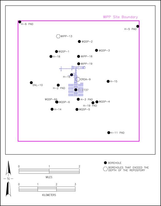
Figure 44-1. Approximate Locations of Unplugged Boreholes
To mitigate the potential for contaminants to migrate toward the accessible environment, the DOE uses established borehole plugging practices (Christensen and Peterson 1981) to limit the volume of water that could be introduced to the repository from the overlying water-bearing zones, and to limit the hypothetical volume of contaminated brine released from the repository to the accessible environment. The governing regulations for plugging and/or abandonment of boreholes are summarized in Table 44-1.
The CRA-2009 monitoring period was from 10/1/2002 through 9/30/2007. Appendix DATA-2009, Attachment A listed the operational monitoring wells within the WIPP vicinity. During the monitoring period, 19 new wells were drilled and put into service, 3 for the shallow water program and 16 for the groundwater program. The shallow water wells were all less than 23.5 meters (m) (77 feet [ft]) in depth. The groundwater-monitoring wells varied from 68.3 m to 414.5 m (224 ft to 1,360 ft) in depth. Sixteen groundwater-monitoring wells were plugged during the monitoring period; all were plugged solid with cement. During this monitoring period, two monitoring wells were plugged back, converted to water wells, and turned over to local ranchers for their use. In addition, one former potash borehole was converted to a groundwater-monitoring well. Appendix DATA-2009, Attachment A provides a description of the wells in the WIPP monitoring system at that time.
Four deep wells (greater than 655.3 m [2,150 ft] in depth), DOE 1, ERDA 9, WIPP 12, and WIPP 13, are required to be plugged in accordance with the State of New Mexico, Oil Conservation Division, Order No. R-111-P. The key provisions of Order No. R-111-P are as follows:
·
A salt protection string of casing must be installed at least 30 m (100 ft) below and not more than 183 m (600 ft) below the base of the salt section. Cementing requirements for both shallow wells (above 1,524 m [5,000 ft]) and deep wells (below 1,524 m [5,000 ft]) above or below the Delaware Mountain Group are specified.
·
All oil and gas wells drilled within the potash area must provide a solid cement plug through the salt section and any water-bearing horizon and prevent liquids or gases from entering the hole above or below the salt section.
·
The fluid used to mix the (plugging) cement must be saturated with salts common to the salt section penetrated, but not more than 3% of calcium chloride by weight of cement wherever possible.
|
Table 44-1. Governing Regulations for Borehole Abandonment
|
Federal or State Land
|
Type of Well or Borehole
|
Governing Regulation
|
Summary of Requirements
|
|
Both
|
Groundwater Wells
|
Well Driller Licensing; Construction, Repair and Plugging of Wells (State of New Mexico 2005, Article 4-140)
|
Any specific plugging requirements and provisions made by the state engineer shall be set forth in the permit.
|
|
Federal
|
Oil and Gas Wells
|
Onshore Oil and Gas Operations (43 CFR 3160) (U.S. Department of the Interior 1983, p. 36583),
Well Abandonment (43 CFR 3162.3-4) (U.S. Department of the Interior 1988a, p. 47765)
|
The operator shall promptly plug and abandon, in accordance with a plan first approved in writing or prescribed by the authorized officer.
|
|
Federal
|
Potash
|
Solid Minerals (Other than Coal) Exploration and Mining (43 CFR 3590) (U.S. Department of the Interior 1988b, p. 39461), Core or Test Hole Cores, Samples, Cuttings (43 CFR 3593.1) (U.S. Department of the Interior 1988c, p. 39461)
|
(b) Surface boreholes for development or holes for prospecting shall be abandoned to the satisfaction of the authorizing officer by cementing and/or casing or by other methods approved in advance by the authorized officer. The holes shall also be abandoned in a manner to protect the surface and not endanger any present or future underground operation, any deposit of oil, gas, or other mineral substances, or any aquifer.
|
|
State
|
Potash
|
Well Driller Licensing; Construction, Repair and Plugging of Wells (State of New Mexico 2005, Article 4-20.2)
|
In the event that the test or exploratory well is to be abandoned, the state engineer shall be notified. Such wells shall be plugged in accordance with Article 4-19.1 so that the fluids will be permanently confined to the specific strata in which they were originally encountered.
|
|
State
|
Oil and Gas Well Outside the Oil-Potash Area
|
Plugging and Permanent Abandonment (State of New Mexico 1996, Rule 202)
|
B. Plugging
(1) Before an operator abandons a well, the operator shall plug the well in a manner that permanently confines all oil, gas and water in the separate strata in which they are originally found. The operator may accomplish this by using mud-laden fluid, cement and plugs singly or in combination as approved by the division on the notice of intention to plug.
|
|
(2) The operator shall mark the exact location of plugged and abandoned wells with a steel marker not less than 10.2 centimeters (4 inches) in diameter set in cement and extending at least 1.2 m (4 ft) above mean ground level. The operator name, lease name and well number and location, including unit letter, section, township and range, shall be welded, stamped or otherwise permanently engraved into the marker's metal.
|
|
Table 44-1.
Governing Regulations for Borehole Abandonment (Continued)
|
Federal or State Land
|
Type of Well or Borehole
|
Governing Regulation
|
Summary of Requirements
|
|
State
|
Oil and Gas Wells Inside the Oil-Potash Area
|
Order No. R-111-P (State of New Mexico 1988)
|
F. Plugging and Abandonment of Wells
(1) All existing and future wells that are drilled within the potash area shall be plugged in accordance with the general rules established by the Division. A solid cement plug shall be provided through the salt section and any water-bearing horizon to prevent liquids or gases from entering the hole above or below the salt selection.
|
|
It shall have suitable proportions-but no greater than three percent of calcium chloride by weight-of cement considered to be the desired mixture when possible.
|
Two of the four deep wells (WIPP-12 and DOE-1) were plugged and abandoned. The New Mexico Office of the State Engineer regulates the drilling, operation, and abandonment of groundwater wells. This agency has regulatory oversight of wells in the controlled area. Although WIPP-12 was plugged with standard cement slurry (no salt), the Office of the State Engineer subsequently agreed that the use of standard cement slurry was acceptable for this instance. DOE-1 was plugged using a salt-saturated cement through the salt section, and a standard cement slurry through the rest of the borehole.
The boreholes not used for monitoring will be plugged at decommissioning. See Appendix BARRIERS-2004, Section BARRIERS-3.2.3
for a detailed discussion of borehole plugs (excluding Section BARRIERS-3.2.3.2). Appendix PA-2009, Section PA-4.2.9
summarizes the representation of the borehole plugs in PA. Fox (Fox 2008, Tables 13 through 17) provided parameter values used in the PA modeling. A listing of all wells drilled in support of the WIPP and other boreholes located within the 16-section Land Withdrawal Area was first included as the CCA, Appendix BH. Appendix DATA-2004, Attachment G provides updates on all of the monitoring wells used in the CCA, Appendix BH, and the new monitoring wells drilled since the initial certification (U.S. DOE 2004) up to the CRA-2009 cutoff date. Appendix DATA-2009, Attachment A lists updates to the borehole information. A detailed discussion of the boreholes used in the groundwater monitoring at the WIPP was presented in Appendix HYDRO-2009, Section HYDRO-5.0.
The information provided in the CRA-2009 demonstrated continued compliance with the section 194.44 criteria.
In its 2010 recertification decision (U.S. EPA 2010a) the EPA stated that the DOE did not report any significant changes to the information on which the EPA based its 1998 Certification and 2004 Recertification Decisions. The DOE did not conduct a new analysis to evaluate the benefit and detriment of engineered alternatives, as defined in 194.44 (b) through (e). The CRA-2009 continued to reflect the EPA's determination that only MgO backfill meets the requirements for an engineered barrier. The EPA did not receive any public comments on the DOE's continued compliance with the requirements of section 194.44. As such, the EPA concluded that the DOE continued to comply with the requirements of 40 CFR 194.44 (U.S. EPA 2010b).
There were no significant changes in the factors on which the EPA bases the determination of compliance with section 194.44. The DOE did not change the engineered barrier type, form, or function and therefore did not conduct a new analysis to evaluate the benefit and detriment of engineered alternatives (originally required by sections 194.44(b) through (e)). The CRA-2014 followed the EPA's determination that only the MgO backfill met the EPA's requirements for an engineered barrier at section 191.14(d).
The DOE had proposed shaft seals, borehole plugs, and panel closures as engineered barriers in the CCA. Changes to the approved engineered barrier that have occurred between the CRA-2009 and the CRA-2014 and changes to other disposal system design features originally proposed as engineered barriers (termed disposal system barriers) are discussed in the following subsections for completeness.
A detailed history of the MgO engineered barrier is presented in Appendix MgO-2009 and describes the placement, function, and experimental activities associated with the barrier since it was first proposed. Appendix MgO-2014 describes in greater detail the changes that occurred between the CRA-2009 and the CRA-2014.
The following developments associated with the MgO engineered barrier that have occurred since the EPA's 2009 Recertification Decision include information from additional analyses and the DOE's planned change notice:
1. The EPA's approval of the DOE's planned change notice for placement of MgO supersacks, which includes:
A. Emplacement of supersacks on every other row unless additional sacks are needed to meet the 1.2 excess factor.
B. Standard supersacks weight of 3,000 pounds.
2. Completion of MgO hydration studies.
3. Refinement of water balance in PA to include the impact of MgO.
The following sections provide additional detail for these changes.
In February 2012, the DOE submitted a planned change notice outlining an alternative placement scheme for MgO supersacks (Franco 2012). In July 2012, the EPA concurred with the emplacement approach in the DOE's change notice (Peake 2012).
The procedure for emplacement of MgO supersacks in the WIPP underground is WP 05-WH1025, titled CH Waste Downloading and Emplacement (WTS 2011). This procedure was changed to initially emplace a 3,000-pound supersack of MgO on every other waste stack or on each waste stack in every other row, rather than placing a supersack on every waste stack. The MgO excess factor is calculated at the end of each shift based on the amount of CPR emplaced during that shift. If the MgO excess factor for the room is less than 1.2, then additional MgO supersacks will be added as specified in the procedure. Additional information relating to this change is found in Appendix MgO-2014, Section MgO-2.1.4.
Hydration studies of MgO have been ongoing since 2000. A historical presentation of these studies is found in Appendix MgO-2009, Section MgO-4.0.
Since the CRA-2009, Xiong (Xiong 2008), Deng et al. (Deng et al. 2009), and Xiong et al. (Xiong et al. 2010) completed these hydration studies (as referenced). Appendix MgO-2014, Section MgO-4.1.1
discusses their results. The conclusion of these studies changed the way MgO is accounted for in actinide solubility calculations. A different MgO hydration phase is now used in solubility calculations for the two brines used in PA. The calculations now predict that the hydration of MgO in Generic Weep Brine will produce brucite and phase 5 instead of brucite and phase 3, and that hydration of MgO in ERDA-6 brine will produce only brucite. The implementation and impacts of this change are described in Appendix MgO-2014, Section MgO-5.0
, and Appendix SOTERM-2014, Section SOTERM 2.3.
The repository water balance implementation was refined in the CRA-2014 PA to include brine and gas producing and consuming reactions in the existing conceptual model. The development of parameters used in the refined water budget implementation is described in Clayton (Clayton 2013). Parameters associated with the water balance refinement implemented in the CRA-2014 PA include those related to iron corrosion, MgO hydration and carbonation. A description of this change and a list of the specific parameters are found in Appendix PA, Section PA-7.1
, and in Camphouse et al. (Camphouse et al. 2013), Section 2.10. The CRA-2014 PA sensitivity analysis concluded that the parameter changes related to MgO in the refined water balance analysis do not have a significant impact on potential releases from the repository (Kirchner 2013).
As stated earlier, the DOE had proposed MgO, shaft seals, borehole plugs, and panel closures as engineered barriers in the CCA. The EPA considered MgO backfill as the only feature that met their requirements for an engineered barrier at section 191.14(d). Since these other features are not recognized by the EPA as meeting the requirements for an engineered barrier under section 191.14(d), they will no longer be discussed in this section. Information relating to borehole plugs can be found in Appendix DATA-2014, Attachment A, "WIPP Borehole Update." Information on the current representation of panel closures in PA can be found in Appendix PA-2014, Section PA-4.2.8
, and in Camphouse et al. (Camphouse et al. 2013), Section 2.1. There have been no changes to the representation of shaft seals in the CRA-2014 PA, nor is there new information to present (Appendix PA-2014, Section PA-4.2.7
).
None of the changes relating to the WIPP engineered barrier impact activities and conditions that demonstrated compliance with section 194.44 criteria documented in prior recertification applications. The impacts of changes relating to the engineered barrier do not require modification of the CCA analysis that evaluated the benefit and detriment of engineered alternatives, as required by 194.44 (b) through (e). The DOE continues to demonstrate compliance with the requirements of section 194.44.
(*Indicates a reference that has not been previously submitted.)
Camphouse, R.C., D.C. Kicker, T.B. Kirchner, J.J. Long, B. Malama and T.R. Zeitler. 2013. Summary Report for the 2014 WIPP Compliance Recertification Application Performance Assessment, Rev. 0. ERMS 560252. Carlsbad, NM: Sandia National Laboratories.* [PDF / Author]
Clayton, D.J. 2013. Justification of Chemistry Parameters for Use in BRAGFLO for AP-164, Revision 1. Memorandum to SNL Records Center dated March 13, 2013. ERMS 559466. Carlsbad, NM: Sandia National Laboratories.* [PDF / Author]
Christensen, C.L., and E.W. Peterson. 1981. "Field-Test Programs of Borehole Plugs in Southeastern New Mexico." The Technology of High-Level Nuclear Waste Disposal Advantages in the Science and Engineering of the Management of High-Level Nuclear Wastes (vol. 1, pp. 354-69). P.L. Hofman and J.J. Breslin (eds.). SAND79-1634C. DOE/TIC-4621. Oak Ridge, TN: Technical Information Center of the U.S. Department of Energy. [Author]
Cohen and Associates. 2008. Review of MgO-Related Uncertainties in the Waste Isolation Pilot Plant (January 24). Vienna, VA: S. Cohen and Associates. [PDF / Author]
Deng, H., Y. Xiong, M. Nemer, and S. Johnsen. 2009. "Experimental Work Conducted on MgO Long-Term Hydration: 2008 Milestone Report." May 27, 2009. ERMS 551421. Carlsbad, NM: Sandia National Laboratories.* [PDF / Author]
Deng, H., Y. Xiong, and M. Nemer. 2007. Experimental Work Conducted on MgO Characterization and Hydration, Milestone Report. ERMS 546570. Carlsbad, NM: Sandia National Laboratories. [PDF / Author]
Deng, H., S. Johnsen, Y. Xiong, G.T. Roselle, and M. Nemer. 2006. Analysis of Martin Marietta MagChem 10 WTS-60 MgO. ERMS 544712. Carlsbad, NM: Sandia National Laboratories. [PDF / Author]
Detwiler, R.P. 2004. Letter to E. Cotsworth (Subject: Response to EPA May 20, 2004, Letter on CRA; 2 Enclosures). 29 September 2004. Carlsbad, NM: U.S. Department of Energy, Carlsbad Field Office. [PDF / Author]
Fox, B. 2008. Parameter Summary Report for the CRA-2009 (Revision 0). ERMS 549747. Carlsbad, NM: Sandia National Laboratories. [PDF / Author]
Franco, J.R. 2012. Letter to A. Perrin (Subject: Planned Change Notice for Placement of MgO Supersacks," with enclosure (Analysis of an alternative placement scheme for MgO supersacks). February 14, 2012. Carlsbad, NM: U.S. Department of Energy Carlsbad Field Office.* [PDF / Author]
Gitlin, B.C. 2006. Letter to D.C. Moody. 28 April 2006. ERMS 543319. Washington, DC: U.S. Environmental Protection Agency, Office of Radiation and Indoor Air. [PDF / Author]
Kirchner, T.B. 2013. Sensitivity of the CRA-2014 Performance Assessment Releases to Parameters, ERMS 560043. Carlsbad, NM: Sandia National Laboratories.* [PDF / Author]
Langmuir, D. 2007. Memorandum to S.L. Ostrow (Subject: Letter Report Review of the SC&A Draft Report "Review of MgO-Related Uncertainties in the Waste Isolation Pilot Plant"). November 4, 2007. Silverthorne, CO: Hydrochem Systems Corporation. [PDF / Author]
Marcinowski, F. 2002. Letter to I. Triay. 15 November 2002. Washington, DC: U.S. Environmental Protection Agency, Office of Air and Radiation. [PDF / Author]
Marcinowski, F. 2004. Letter to R.P. Detwiler (2 Enclosures). 26 March 2004. ERMS 534327. Washington, DC: U.S. Environmental Protection Agency, Office of Air and Radiation. [PDF / Author]
Moody, D.C. 2006a. Letter to E. Cotsworth (Subject: Transmittal of Planned Change Request; 1 Enclosure). 10 April 2006. ERMS 543262. Carlsbad, NM: U.S. Department of Energy, Carlsbad Field Office. [PDF / Author]
Moody, D.C. 2006b. Letter to J. Reyes (Subject: Uncertainty Analysis for Planned Change Request on Magnesium Oxide (MgO) Emplacement; 4 Enclosures). November 21, 2006. Carlsbad, NM: U.S. Department of Energy, Carlsbad Field Office. [PDF / Author]
Moody, D.C. 2007a. Letter to J. Reyes (Subject: Modification to Condition 1 of Certification Decision). 11 January 2007. ERMS 545491. Carlsbad, NM: U.S. Department of Energy, Carlsbad Field Office. [PDF / Author]
Moody, D.C. 2007b. Letter to J. Reyes (Subject: Requesting Withdrawal of Panel Closure Change Request). 9 October 2007. Carlsbad, NM: U.S. Department of Energy, Carlsbad Field Office. [PDF / Author]
Peake, T. 2012. Email to J.R. Franco (Subject; "Magnesium Oxide Supersack Size Reduction and Alternative Emplacement Plan"). July 13, 2012. Washington, DC: U.S. Environmental Protection Agency, Office of Radiation and Indoor Air.* [PDF / Author]
Reyes, J. 2007. Letter to D. Moody (Subject: Response to DOE's letter dated January 11, 2007). 22 February 2007. ERMS 545394. Washington, DC: U.S. Environmental Protection Agency, Office of Air and Radiation. [PDF / Author]
Reyes, J. 2008. Letter to D.C. Moody (5 Enclosures). 11 February 2008. Washington, DC: U.S. Environmental Protection Agency, Office of Air and Radiation. [PDF / Author]
Sandia National Laboratories (SNL). 1996. Implementation of Chemical Controls Through a Backfill System for the Waste Isolation Pilot Plant (WIPP). SAND96-2656A. ERMS 242847. Albuquerque, NM: Sandia National Laboratories. [PDF / Author]
State of New Mexico. 1988. Order R-111-P: Potash Areas of Eddy and Lea Counties, NM. Case 9316, Revision to Order R-111-P. April 21, 1988. Oil Conservation Division, Energy, Minerals, and Natural Resources Department. [PDF / Author]
State of New Mexico. 1996. Title 19, Chapter 15, Part 4, Rule 202, Plugging and Permanent Abandonment. February 1, 1996. Oil Conservation Division, Energy, Minerals, and Natural Resources Department. [PDF / Author]
State of New Mexico. 2005. 19.27.4 NMAC: Well Driller Licensing; Construction, Repair and Plugging of Wells. August 31, 2005. Oil Conservation Division, Energy, Minerals, and Natural Resources Department. [PDF / Author]
Triay, I. 2002. Letter to F. Marcinowski (Subject: Request Planned Change to Panel Closure System). 7 October 2002. Carlsbad, NM: U.S. Department of Energy, Carlsbad Field Office. [PDF / Author]
Trinity Engineering Associates (TEA). 2004. Review of Effects of Supercompacted Waste and Heterogeneous Waste Emplacement on WIPP Repository Performance (March 17). Cincinnati: Trinity Engineering Associates. [PDF / Author]
U.S. Department of Energy (DOE). 1996. Title 40 CFR Part 191 Compliance Certification Application for the Waste Isolation Pilot Plant (October). 21 vols. DOE/CAO-1996-2184. Carlsbad, NM: Carlsbad Area Office. [Author]
U.S. Department of Energy (DOE). 2004. Title 40 CFR Part 191 Compliance Recertification Application for the Waste Isolation Pilot Plant (March). 10 vols. DOE/WIPP 2004-3231. Carlsbad, NM: Carlsbad Field Office. [Author]
U.S. Environmental Protection Agency (EPA). 1993. "40 CFR Part 191 Environmental Radiation Protection Standards for the Management and Disposal of Spent Nuclear Fuel, High-Level and Transuranic Radioactive Wastes: Final Rule." Federal Register, vol. 58 (December 20, 1993): 66398-416. [PDF /Author]
U.S. Environmental Protection Agency (EPA). 1996. "40 CFR Part 194: Criteria for the Certification and Re-Certification of the Waste Isolation Pilot Plant's Compliance with the 40 CFR Part 191 Disposal Regulations; Final Rule." Federal Register, vol. 61 (February 9, 1996): 5224-45.
[PDF /Author]
U.S. Environmental Protection Agency (EPA). 1998. "40 CFR Part 194 Criteria for the Certification and Recertification of the Waste Isolation Pilot Plant's Compliance with the Disposal Regulations: Certification Decision; Final Rule." Federal Register, vol. 63 (May 18, 1998): 27353-406. [PDF /Author]
U.S. Environmental Protection Agency (EPA). 2004. Discussion of Major Issues Associated with EPA's Compressed Waste Review. ERMS 534327. Washington, DC: Office of Air and Radiation. [PDF /Author]
U.S. Environmental Protection Agency (EPA). 2006. "40 CFR Part 194: Criteria for the Certification and Recertification of the Waste Isolation Pilot Plant's Compliance with the Disposal Regulations: Recertification Decision" (Final Notice). Federal Register, vol. 71 (April 10, 2006): 18010-021.* [PDF
/Author]
U.S. Environmental Protection Agency (EPA). 2008. Overview Summary of Planned Change Request Decision. Washington, DC: Office of Radiation and Indoor Air. [PDF / Author]
U.S. Environmental Protection Agency (EPA). 2010a. "40 CFR Part 194 Criteria for the Certification and Recertification of the Waste Isolation Pilot Plant's Compliance with the Disposal Regulations: Recertification Decision; Final Notice." Federal Register, vol. 75 (November 18, 2010): 70584 - 595.* [PDF / Author]
U.S. Environmental Protection Agency (EPA). 2010b. "Recertification CARD Nos. 44: Engineered Barriers." 2009 Compliance Recertification Application (2009 CRA) Compliance Application Review Documents (CARD) Nos. 44. EPA Docket FDMS Docket ID No. EPA-HQ-OAR-2009-0330 (November 18, 2010). Washington, DC: Office of Radiation and Indoor Air.* [PDF / Author]
Wall, N.A. 2005. Preliminary Results for the Evaluation of Potential New MgO (January 27). ERMS 538514. Carlsbad, NM: Sandia National Laboratories. [PDF / Author]
Washington TRU Solutions (WTS). 2003. Specification for Prepackaged MgO Backfill (Rev. 5). D-0101. Carlsbad, NM: Washington TRU Solutions. [PDF / Author]
Washington TRU Solutions (WTS). 2011. CH Waste Downloading and Emplacement. WP 05-WH1025, Carlsbad, NM: Nuclear Waste Partnership LLC.* [PDF / Author]
Xiong, Y.-L. 2008. "Thermodynamic Properties of Brucite Determined by Solubility Studies and Their Significance to Nuclear Waste Isolation." Aquatic Geochemistry. Vol. 14, no. 3, 223-238.* [Author]
Xiong, Y.-L., H.-R. Deng, M.B. Nemer, and S. Johnsen. 2010. "Experimental Determination of the Solubility Constant for Magnesium Chloride Hydroxide Hydrate (Mg3Cl(OH)5·4H2O, Phase 5) at Room Temperature, and Its Importance to Nuclear Waste Isolation in Geological Repositories in Salt Formations," Geochimica et Cosmochimica Acta. Vol. 74, no. 16, 4605- 4611.* [Author]